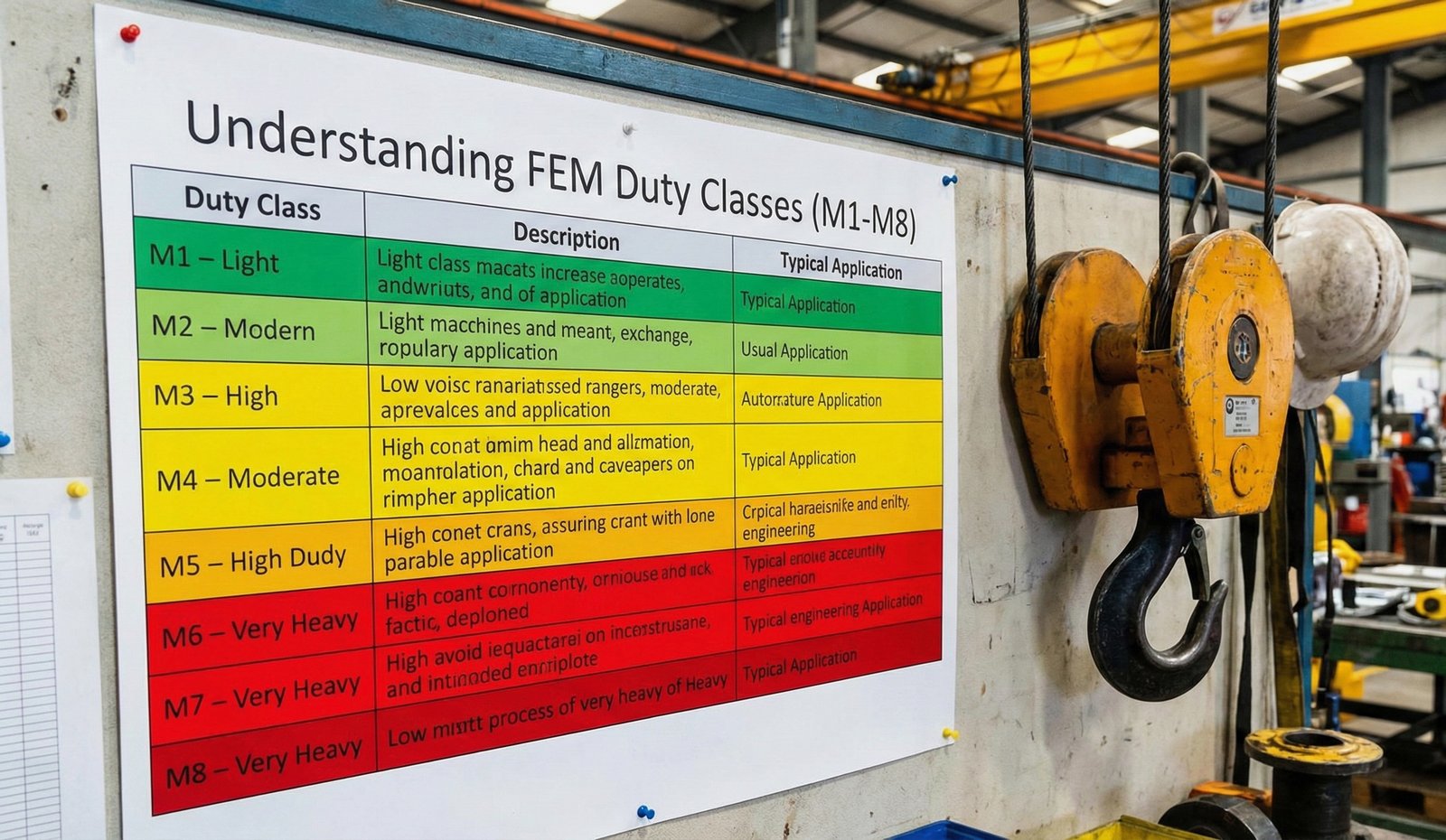
Meet the 4 Global Crane Standards
When you walk onto an industrial shop floor, every overhead crane looks like a steel box girder carrying a motorized trolley. But beneath the yellow paint, the internal web stiffening, flange plate thicknesses, and weld fatigue allowances were calculated according to one of four major global rulebooks:
IS 807 & IS 3177
Bureau of Indian StandardsThe Heavyweight Veteran: Built on working stress design (allowable stress). Extremely conservative deflection rules (L/750 to L/900) and Class 1 to 4 groupings. Excellent for heavy fabrication and public tenders.
FEM 1.001 / EN 13001
Federation Europeenne de la ManutentionThe Precision Mathematician: Highly optimized European code based on mechanism groups (1Bm to 5m) and load spectrum factors (K1 to K4). Reduces girder deadweight while strictly enforcing fatigue life.
ISO 4301 / ISO 8686
International Organization for StandardizationThe Universal Translator: The modern global benchmark classifying crane mechanisms from M1 to M8 based on state of loading and total number of operating cycles (U0 to U9).
CMAA Spec 70 / 74
Crane Manufacturers Assoc. of AmericaThe American Standard: Segregates cranes into six distinct Service Classes (Class A through Class F). Widely used in power generation, paper mills, and North American process plants.
The Rosetta Stone: Duty Class Equivalence Matrix
If your tender calls for an IS Class 3 crane, what European FEM or ISO model should you accept? Use this master conversion matrix to compare bids like-for-like:
| Duty & Application | ISO 4301 | FEM 1.001 | IS 807 / 3177 | CMAA 70 | Typical Design Life |
|---|---|---|---|---|---|
|
Standby / Powerhouse Maintenance
|
M1 – M2 | 1Dm – 1Cm | Class 1 | Class A (Standby) | 500 – 1,000 hrs |
|
Light Workshop & Assembly
|
M3 – M4 | 1Bm – 1Am | Class 2 | Class B / Class C | 1,600 – 3,200 hrs |
|
General Production (Machine Shop)
|
M5 | 2m | Class 2 / Class 3 | Class D (Heavy) | 6,300 hrs |
|
Foundry, Scrap Yard & Heavy Fab
|
M6 – M7 | 3m – 4m | Class 3 / Class 4 | Class E (Severe) | 12,500 – 25,000 hrs |
|
Steel Mill Ladle, Magnet & Grab
|
M8 | 5m | Class 4 (Extra Heavy) | Class F (Continuous) | 50,000+ hrs |
The Physics of Deflection: Why Girders Sag
Imagine placing a heavy 20-ton trolley in the exact center of a 24-meter box girder bridge. The girder bends downward under the immense weight.
If the girder sags too much, the trolley is essentially forced to travel uphill every time it tries to move away from the center! This burns out cross-travel gearmotors, causes wheel flanges to grind against the rail, and introduces violent dynamic oscillations.
How Much Does a 20-Meter Girder Bend Under Load?
💡 The Pre-Camber Secret: High-end fabricators plasma-cut the web plates with an artificial upward arch (pre-camber). When the full Safe Working Load is applied, the girder bends down to become perfectly horizontal!
The Silent Killer: Cyclic Fatigue & Weld Notches
Here is a counter-intuitive truth that shocks many new engineers: over 85% of crane structural failures occur at stress levels far below the yield strength of the steel.
If you lift 10 Tons with an E250 steel plate (yield strength = 250 MPa), the static bending stress might only be 95 MPa—seemingly safe with a 2.6x safety margin. But after 1.5 million lift cycles, microscopic stress concentrations at the toe of fillet welds develop fatigue micro-fissures that suddenly propagate into catastrophic brittle fractures.
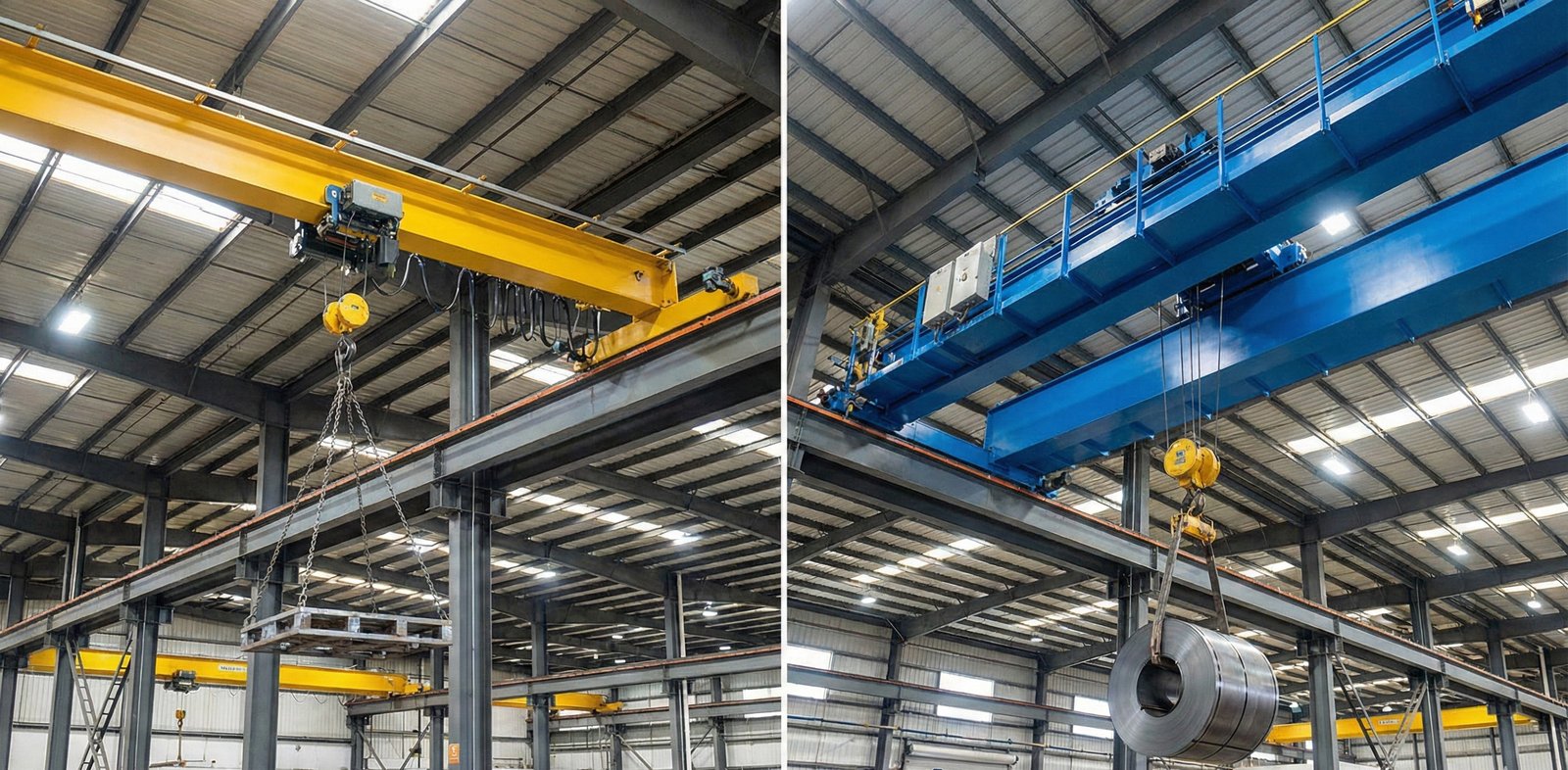
How FEM & ISO Solve Fatigue (The Detail Category)
Unlike older codes that only checked static allowable stress, modern standards like FEM 1.001, EN 13001, and ISO 8686 evaluate the Stress Range (Δσ) across Wöhler S-N fatigue curves:
- Detail Category K0 (Full-Penetration Butt Welds, Ground Flush): Highest fatigue endurance limit (≈ 160 MPa).
- Detail Category K3 (Continuous Automatic Fillet Welds): Moderate fatigue limit (≈ 100 MPa).
- Detail Category K5 (Intermittent Stitch Welds / Abrupt Plate Stiffener Terminations): Severely degraded fatigue limit (≈ 50 MPa).
Rule of Thumb for High-Duty Cranes (M7 & M8)
Never permit intermittent stitch welding on main girder flanges for Class 3/4 or M6–M8 cranes. All tension flange stiffeners must be welded with continuous welds and inspected with 100% Ultrasonic Testing (UT) or Magnetic Particle Testing (MPT).
How to Write an Unambiguous Crane Specification
To protect your project from procurement disputes, never write "Crane shall be heavy duty" or just "Class 2" in your purchase inquiry. Use this exact 4-point specification template:
// RECOMMENDED TENDER CLAUSE
1. Crane Structural Design Standard: IS 807:2006 / ISO 4301-1
2. Crane Overall Group: ISO Class M5 (FEM 2m)
3. Hoist Mechanism Group: ISO Class M6 (FEM 3m, 40% CDF, 300 starts/hr)
4. Vertical Deflection Limit: Maximum Span / 900 under SWL + Trolley Weight
5. Web Plate Slenderness (d/t): Stiffened per IS 807 Section 22 to prevent elastic web buckling
Explore the Interactive Design Toolkit
Test these structural formulas on your own crane dimensions using our free online calculators:
Duty Class Calculator
Determine ISO/FEM mechanism group from operating hours and load spectrum.
Deflection & Camber Tool
Compute allowable IS 3177 deflection and parabolic camber curve.
Box Girder Stiffener Tool
Calculate web buckling slenderness limits and stiffener spacing.
Motor Power Sizing Tool
Compute required kW ratings for hoist, CT, and LT travel drives.
Ready to Calculate Your Bridge Deflection?
Input your crane span, live load, and girder moment of inertia to verify compliance against IS 807 and FEM limits.
Launch Deflection Calculator